
Load Management
A summary of Evnex's local load management features and requirements.

Load management is a smart EV charging feature available with Evnex chargers that safely and efficiently distributes your available electrical capacity across multiple EV chargers connected to a common electrical supply.
In a residential environment, this means you can charge multiple vehicles simultaneously without the risk of blowing the supply fuse or overloading your switchboard. Similarly, in a commercial environment, the system will maximise charging speed across multiple vehicles based on the available electrical capacity.
Compared to many common appliances or equipment, EV chargers draw significant current for long periods of time. Based on max. demand calculations, the vast majority of electrical supplies in existing homes or commercial buildings have not been designed to account for the added demand of multiple EV chargers operating at full capacity simultaneously. Meaning that unless costly supply upgrades are undertaken, the existing electrical infrastructure could overload as a result of charging EVs. In many cases these buildings do however have some capacity available for charging when managed properly. This is where Evnex load management can help.
Our dynamic solution will take into account the local supply capacity, the building's demand profile and the proposed operational usage. Each site will have its unique set of circumstances, and the system can be designed to maximise charging whilst minimising costs.
There are two versions of this feature, with differing advantages and installation requirements. Below are key points for you to consider when setting up your EV charging infrastructure to take advantage of the best load management solution for your situation.
1. Local Load Management
Evnex local load management (LLM) is the preferred method. It is the most reliable solution as the system is managed locally, rather than a remote server, to maintain safe and reliable operation, even when connection to the internet is lost temporarily.
This stand-alone system operates independently of building management systems (BMS), inverters or home battery systems and is designed to work on most sites to alleviate the risks of supply overload.
The system can either be configured with a static upper limit, applicable where a portion of the total supply capacity can be guaranteed and allocated to EV charging; or with a dynamic upper limit, applicable where a given electrical supply must be monitored, and collective charging output adjusted in real-time to account for other building loads.
Static configuration will evenly distribute available capacity across all chargers within the configured load-group. The current limit of this group is set during commissioning and chargers connected will not exceed this collective current limit. However, this configuration does not monitor the supply and is purely set to maintain the allocated total group limit. Therefore, it is best suited for dedicated EV sub-boards or situations where a portion of the total supply is guaranteed.
Dynamic configurations offer the same functionality as the static configuration but introduces real-time supply monitoring. This allows multiple chargers to be connected to electrical supplies that don't have consistent spare capacity for the added chargers. It safeguards a given supply or switchboard that also supplies other loads from overload, without the need to increase capacity.
For either configuration, any given charger* within the load-group can be configured as the primary control charger (server). This charger controls the output and behaviour of all other secondary units in the load-group.
The dynamic configuration requires CTs to be installed at the overall supply or switchboard that the system is set to safeguard. To ensure reliability, these CTs must be hardwired to the server charger, via overall screened twisted pair instrumentation cable. This solution is limited to 400A supplies, currently.
Either configuration allows for a combination of single-phase and three-phase chargers connected to the same load-group and will monitor each phase individually. However, single-phase groups generally deliver better results.
Multiple load management groups and configurations may be deployed at a single site, however it's important to note, multiple dynamic groups cannot be set up to monitor the same supply phase. In other words, there can only be one CT per phase maximum.
E2 Core chargers cannot be configured as the primary control unit.
E2 Flex chargers cannot be configured as either primary or secondary unit.
LLM Solar Charging & Load Profiles
Evnex chargers, when configured as Dynamic LLM, also allow you to take advantage of locally generated Solar Charging energy export across all chargers in a given load-group, provided adequate export is available.
User-created load profiles can be set to determine the available power to balance from (e.g. max. 50 Amps during the day, 200 Amps at night).
Charger Communications
All Evnex chargers must be connected to the internet to allow for initial commissioning and configuration and to enable reporting, control functions and remote support. This can be achieved via integral SIM cards (excl. E2 Core), local Wi-Fi (or Ethernet -- X-Series only).
For load management the chargers also require local comms between all chargers in a given load group. This can be achieved via local Wi-Fi, integral P2P Wi-Fi (or Ethernet -- X-Series only)
While local Wi-Fi (or ethernet) is recommended, P2P (point-to-point), is a great solution for smaller load groups where chargers are in close proximity to each other at locations where local Wi-Fi (or ethernet) is not available. For P2P Wi-Fi the server unit will create its own access point (AP) for other chargers to connect to. It is important that all chargers are within ~15m line-of-sight to this server unit.
As long as local comms are maintained, the LLM system will maintain safe and reliable operation even when internet connection is lost temporarily. In the event that local comms are lost to a given charger, the system will revert to a 6A per charger, per phase fail-safe limit.
Examples of Dynamic (monitored) LLM configurations.
Examples below show wiring and connection for various scenarios and configurations of a dynamic LLM setup. Local comms can also be achieved via P2P Wi-Fi as mentioned above but not shown in the examples. The same can be applied to static configurations. For these. CTs and instrumentation cable should be ignored.
For further information or help with your design please contact Evnex support or the installation team.
Example 1
-
Single-phase chargers
-
One single-phase load group
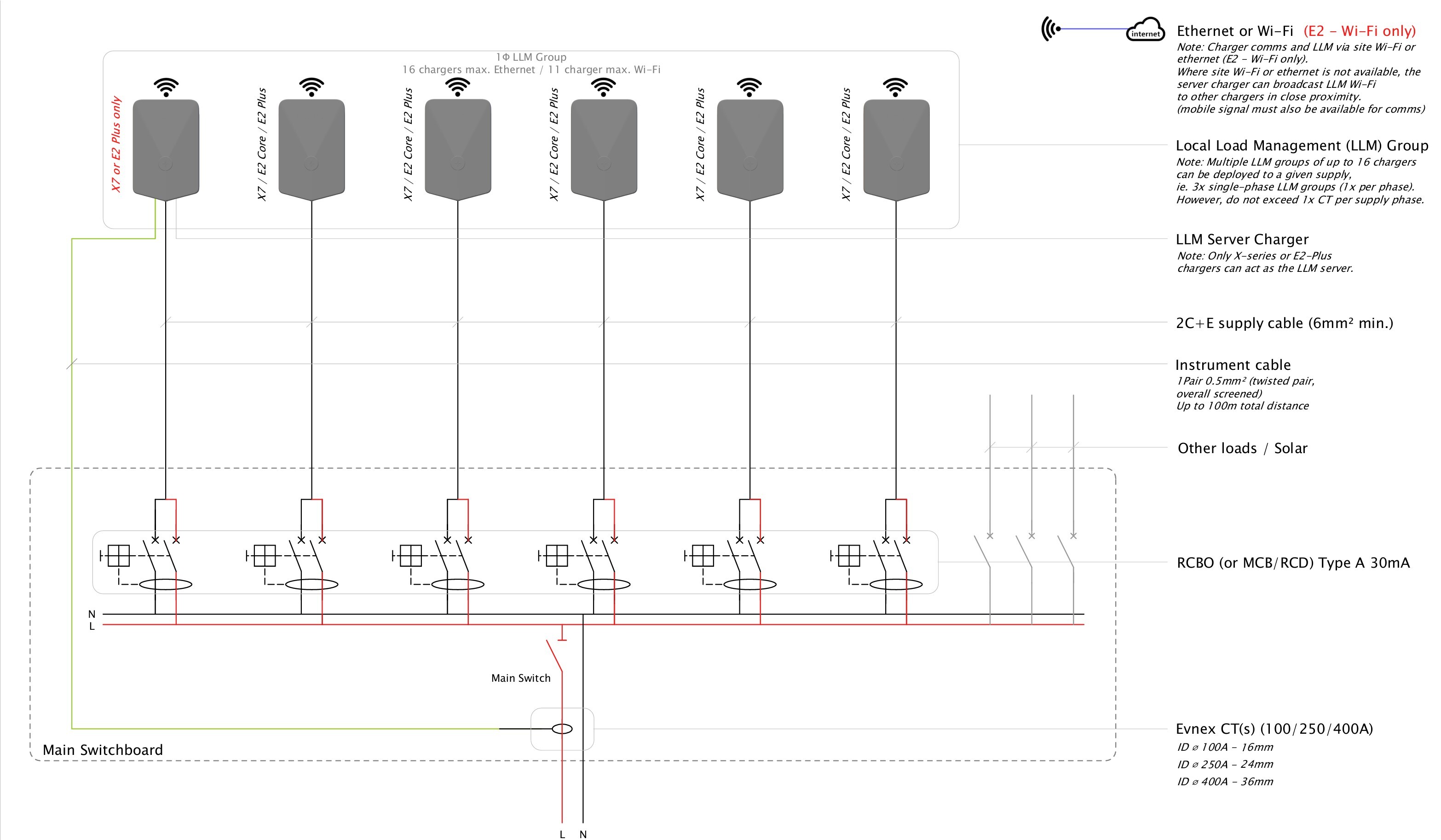
LLM Single-phase, Single Load Group
Example 2
-
Three-phase chargers
-
One three-phase load group
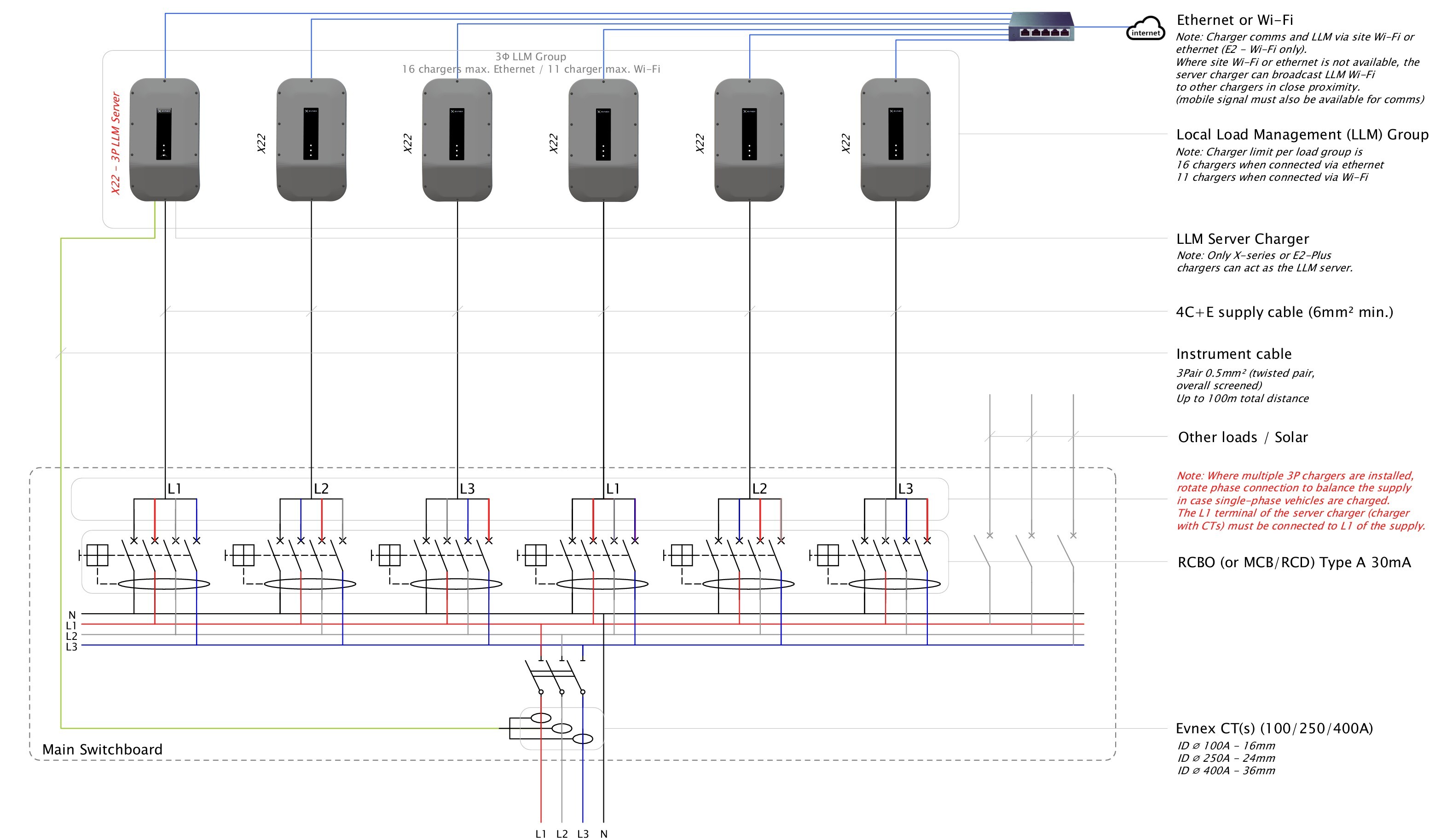
LLM Three-phase, Single Load Group
Example 3
-
Single-phase and three-phase chargers
-
One three-phase load group
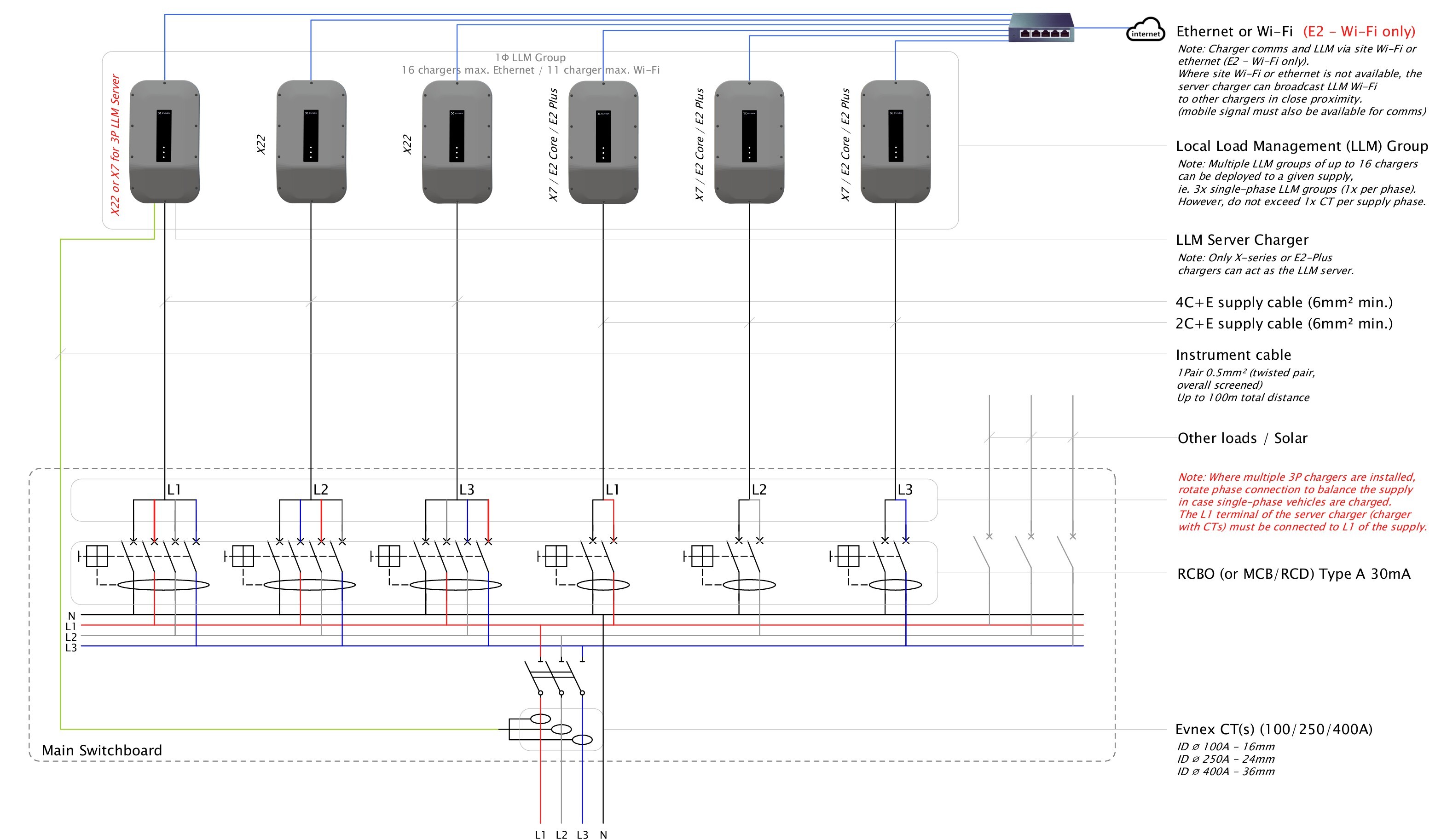
LLM Single and Three-phase chargers, Single Load Group
Example 4
-
Single-phase chargers.
-
Multiple single-phase load groups
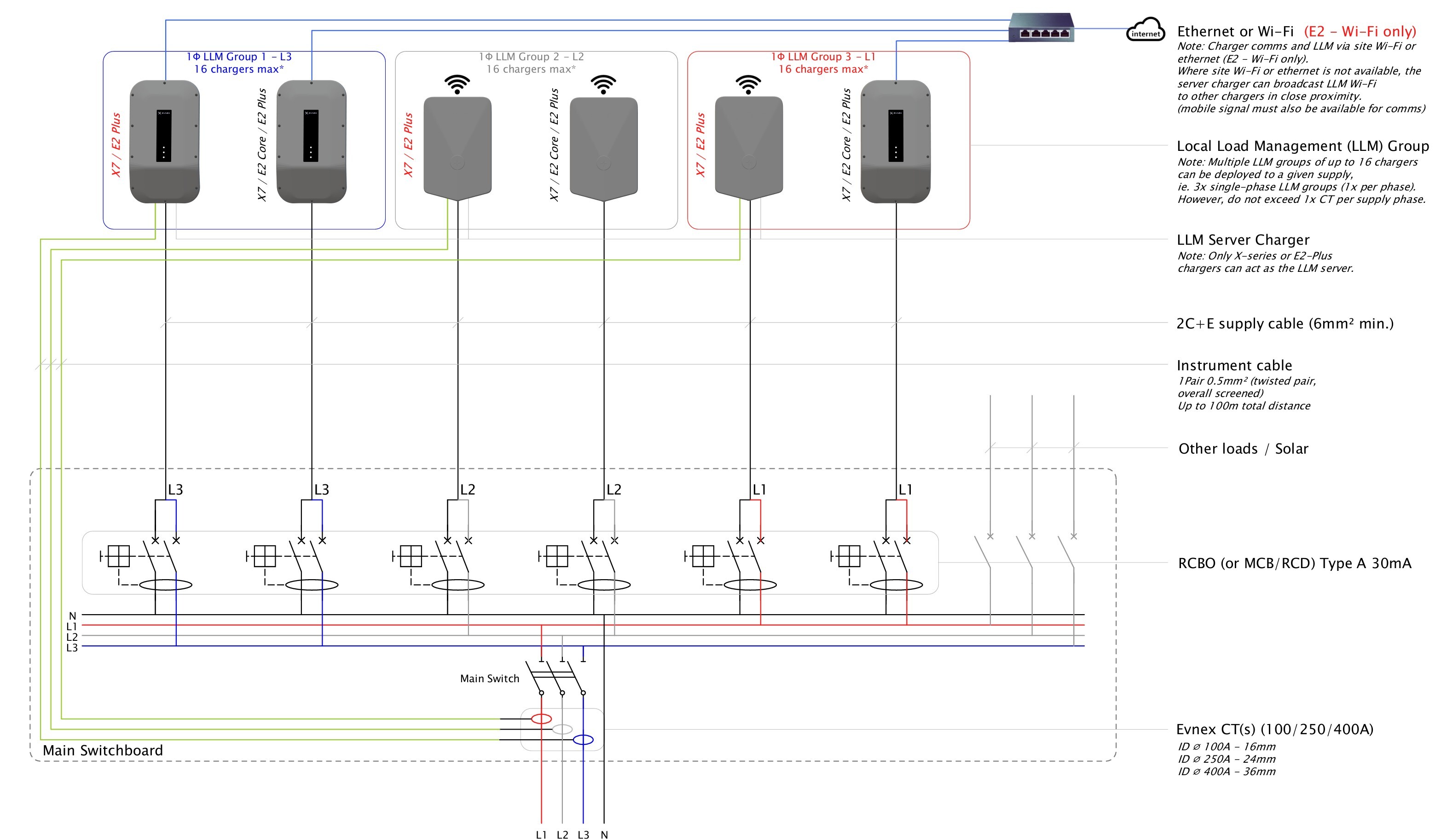
LLM Single-phase Chargers, Multiple Load Groups
Requirements for Local Load Management
-
All chargers require an internet connection and local comms, this may be achieved by a shared method (e.g. Local Wi-Fi).
-
For P2P Wi-Fi groups, the primary unit should be the charger closest to the physical centre point of the group it controls and in no case further away than ~15m line-of-sight from other chargers in the group.
-
The collective upper limit for a given load group is set during commissioning, e.g. 200A per phase between all chargers in the group.
-
One of the chargers in each load group must be set as the primary control unit (server).
-
For dynamic configurations, the server charger requires an overall screened, twisted pair instrumentation cable to be run to the supply to be monitored. The number of pairs depends on CTs to be installed (1 pair per CT). Insulation of this cable must be appropriately rated (≥230/400V) for the maximum voltage present unless other means to comply with AS/NZS:3000 can be achieved.
-
The Evnex-supplied CT(s) must be installed to the phase conductor(s) of the supply to be monitored. (1x CT for single-phase groups and 3x CTs for three-phase groups).
-
CTs currently available are 100A (16mm ID), 250A (24mm ID) and 400A (36mm ID).
-
The load group will dynamically adjust collective output of all chargers, set during commissioning, to ensure this limit isn't exceeded. For dynamic configurations, this will account for other loads, provided these loads are connected to the monitored supply.
-
Alternatively, the group can be set up for a static upper supply limit. This would eliminate the need for the CTs, and instrumentation cable, however the supply is not monitored and the assigned capacity for the load group must be available at all times.
-
All load management sites must be configured by Evnex remotely prior to first use and it is vital to accurately record which supply phase each charger is connected to.
-
Where multiple single-phase or three-phase chargers are connected to a common three-phase supply, it is highly recommended that phases are rotated at the charger terminals, to account for single-phase vehicles to be charged.
-
The maximum number of chargers on a single load group is 16 when connected via Ethernet or 11 when connected via Wi-Fi.
-
The minimum allocated output per charger should be 10A but in no case less than 6A per charger, per phase.
Evnex Load Management Hub (ELMH)
This configuration is still under development but will allow for multi-layered LLM to be deployed across large and complex sites where monitoring of overall supply as well as multiple sub-boards is required.
The system is highly configurable and load management is orchestrated by the ELMH independent of chargers connected to the system.
Internet and local comms are required across all chargers, the ELMH and monitoring equipment and final configuration is exclusively performed by Evnex.
For more information, contact the Evnex team.
2. Cloud-Based Load Management
This legacy configuration is not recommended for deployment for new sites as LLM has several advantages. If your site has constrains that means Evnex's LLM is not viable please get in touch with the Evnex team to discuss cloud-based load management.
This type of load management system relies on a static upper supply limit set during commissioning similar to the static LLM configuration but relies on a continuous connection to Evnex's online control portal CP-Link via a reliable and fast internet connection.
It does not offer any dynamic supply monitoring solution.
Cloud-Based Load Management Summary
-
Each charger must be connected to the internet via a reliable Wi-Fi or Ethernet connection. A cellular connection is not preferable and should only be used where reception is very strong and reliable.
-
The collective upper limit for a given load group is set during commissioning, e.g. 100A per phase between all chargers in the group.
-
The allocated supply limit capacity must be available at all times as the supply is not monitored.
-
The load group will dynamically adjust output to ensure this limit isn't exceeded.
-
For three-phase chargers, the load group will not distinguish between single or three-phase vehicles plugged in and will assume that loads are equal on all three phases and adjust output accordingly.
-
Where multiple single-phase or three-phase chargers are connected to a common three-phase supply, it is highly recommended that phases are rotated at the charger terminals, to account for single-phase vehicles to be charged.
-
The minimum allocated output per charger should be 10A per phase.
-
Best results for supply distribution are achieved using single-phase chargers only and setting up a load group per phase.
-
The maximum number of chargers connected to a given load group is 10.
-
Multiple load groups can be set up on a given supply.
Updated 3 months ago